Slip Ring Motor Starter Circuit Diagram
Difference between slip ring & squirrel cage induction motor with Synchronous motor starting methods instrumentation tools [diagram] wiring diagram slip ring motor resistance starter
Synchronous Motor Starting Methods Instrumentation Tools
Electrical schematic – motor starting system – slip ring motor starting 12+ slip ring motor control diagram Concepts of slip rings and brush assembly in three phase induction
[diagram] wiring diagram slip ring motor resistance starter
Slip ring starter phase rotor power three control diagram diagramsThree phase motor starter wiring diagram for 3 phase motor start up and Motor synchronous starting methods slip ring method induction resistance rotor speed electrical self torque principle working fig rotate engineering engineeringtutorialElectrical standards: slip ring induction motors starting; slip ring.
55 slip ring motor starter wiring diagram wiring diagram planStarter motor slip ring induction used type delta star contactor circuit Motor slip induction ring cage between difference squirrel circuit three poles stator[diagram] wiring diagram slip ring motor resistance starter.

Slip ring induction motor
Slip ring motor rotor motors everything ever need know diagram ll resistance result addedHow to make slip ring motor connection diagram Slip ring motor starter control circuit diagramMedium voltage soft starter for heavy-duty motor control.
[diagram] wiring diagram slip ring motor resistance starterInduction phase learnchannel Motor rotor circuit wound power electrical diagram control schematic induction bank wiring automatic hoist ac resistors guide used step electronics[diagram] wiring diagram slip ring motor resistance starter.
An electrical circuit diagram showing the various components
Outstanding slip ring motor connection diagram 30 amp rv plugSelf start 3-φ induction motor slip-ring wound rotor starter [diagram] wiring diagram slip ring motor resistance starter[get 27+] motor control slip ring motor starter wiring diagram.
6.6kv slip ring induction motor liquid starterGuide to the power circuit and control circuit of the wound rotor ac Everything you’ll ever need to know about slip ring motorsSlip ring motor starter circuit diagram.

Motor ring starter slip diagram schematic magna generation start system speed
Self start 3-φ induction motor slip-ring wound rotor starterRotor resistance or slip ring... Slip ring motor starter wiring diagramSlip rings three motor induction rotor phase wound ring brush circuit concepts assembly rotating machine electrical fig engineering stationary whenever.
Magna start – new generation slip-ring motor starterGeschlossen blauwal innere slip ring motor diagram generator code Wiring diagram slip ring motorStarter slip 6kv induction.

[diagram] wiring diagram slip ring motor resistance starter
What are the type of starter used for slip ring induction motor?Working principle of 3 phase slip ring induction motor Electrical automation slipring.
.


Slip Ring Motor Starter Control Circuit Diagram - Circuit Diagram

Medium voltage soft starter for heavy-duty motor control | EEP
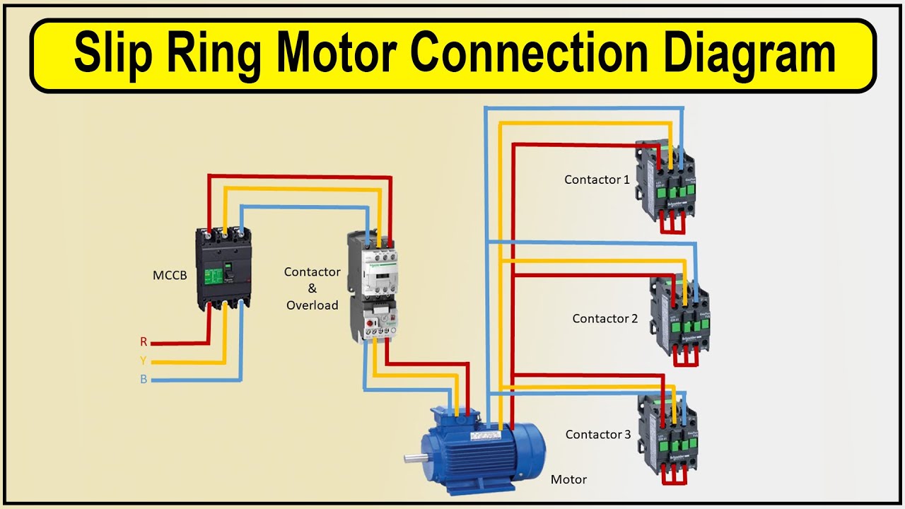
![[DIAGRAM] Wiring Diagram Slip Ring Motor Resistance Starter - MYDIAGRAM](https://i.ytimg.com/vi/c30H-UI6MI4/maxresdefault.jpg)
[DIAGRAM] Wiring Diagram Slip Ring Motor Resistance Starter - MYDIAGRAM

three phase motor starter wiring diagram for 3 phase motor start up and

Concepts Of Slip Rings And Brush Assembly In Three Phase Induction
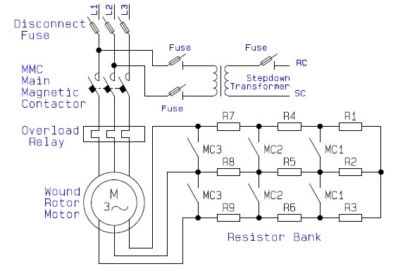
Guide to the Power Circuit and Control Circuit of the Wound Rotor AC

Synchronous Motor Starting Methods Instrumentation Tools